Antares
Antares
en
en
  • Getting Started
    • Account Registration
    • Create App
    • Add Devices to the Application
    • Installation Board and Library
      • ESP8266
      • ESP32
      • STM32
    • Arduino IDE Installation
    • Arduino Library Installation
      • Antares LoRaWAN
      • Antares Wi-Fi HTTP
      • Antares Wi-Fi MQTT
      • DHT11 Sensor Library
      • Adafruit SSD1306
    • STM32 Cube IDE Installation
    • Expansion Pack I-CUBE-LRWAN Installation
    • Software Installation
      • MQTTX Installation
      • Postman Installation
      • Operating System (OS) on SD Card Installation
    • Quickstart
  • Antares Insight Hub
    • Getting Started
      • Request Demo
      • Request Free Trial
    • Usecase
      • Power Meter
        • Power Meter Usecase Prerequisites
        • Power Meter Device Recommendation
        • Payload Example Power Meter
        • Setup Device Threshold Power Meter
      • Water Meter
        • Water Meter Usecase Prerequisites
        • Water Meter Device Recommendation
        • Payload Example Water Meter
        • Setup Device Threshold Water Meter
      • Water Level
        • Water Level Usecase Prerequisites
        • Water Level Device Recommendation
        • Payload Example Water Level
        • Setup Device Threshold Water Level
      • Environment Monitoring
        • Prerequisites for Use of Environmental Monitoring
        • Environment Monitoring Device Recommendation
        • Payload Example Environment Monitoring
        • Setup Device Threshold Environment Monitoring
    • Settings
      • Manage Alert Recipient (Telegram)
      • Manage User
      • Roles
  • Subscription and Payment
    • Platform
      • How to Use Platform Packages
      • How to Purchase a Platform Subscription
        • Payment Using Antares Coins
        • Payment Using Virtual Account
          • Mandiri Bank
          • Permata Bank
          • BRI Bank
          • BNI Bank
        • Payment Using e-Wallet (LinkAja)
        • Payment Using Credit Cards (CC)
      • Procedure for Renewing a Platform Subscription
      • Procedure for Changing Platform Subscription
    • Connectivity
      • How to Use Connectivity Packages
      • How to Purchase a Connectivity Subscription
        • Payment Using Antares Coins
        • Payment Using Virtual Account
          • Mandiri Bank
          • Permata Bank
          • BRI Bank
          • BNI Bank
        • Payment Using e-Wallet (LinkAja)
        • Payment Using Credit Cards (CC)
      • Procedure for Renewing a Platform Subscription
      • Procedure for Changing Connectivity Subscription
    • Antares Coins
      • Antares Coins Top Up Payment Procedures
        • Payment Using Virtual Account
          • Mandiri Bank
          • Permata Bank
          • BRI Bank
          • BNI Bank
        • Payment Using e-Wallet (LinkAja)
        • Payment Using Credit Cards (CC)
  • Code and library examples
    • ESP8266 (Wi-Fi)
      • General Prerequisites ESP8266 Wi-Fi
      • ESP8266 (Wi-Fi) HTTP Protocol
        • Sending Simple Data to Antares with HTTP Protocol
        • Retrieve the Last Data from Antares Server with HTTP Protocol
        • Simple Project ESP8266 HTTP Antares
          • Periodic Post DHT 11 Data
          • Post DHT 11 Data with Push Button
          • Post DHT 11 data and Display on OLED
          • Get Data displayed on OLED
          • Post and Get DHT 11 Data displayed on OLED
          • Controlling Relays and LEDs Through Get Commands
      • ESP8266 (Wi-Fi) MQTT Protocol
        • Sending Simple Data to Antares with the MQTT Protocol
        • Retrieve Last Data from Antares Server with MQTT Protocol
        • Simple Project ESP8266 MQTT Antares
          • Periodic Send DHT 11 Data
          • Send DHT 11 Data with Push Button
          • Send DHT 11 data and display on OLED display
          • Retrieve Data displayed on OLED Display
          • DHT 11 Send Data and Retrieve Data displayed on OLED Display
          • Controlling Relays and LEDs Through Get Commands
    • Arduino Uno
      • Arduino IDE Installation
      • Antares Ethernet Shield Library Installation
      • Configuration
      • Send Simple Data to Antares
    • ESP32 (Wi-Fi)
      • General Prerequisites ESP32 Wi-Fi
      • ESP32 (Wi-Fi) HTTP Protocol
        • Sending Simple Data to Antares with HTTP Protocol
        • Retrieve the Last Data from Antares Server with HTTP Protocol
        • Simple Project Lynx-32 HTTP Antares
          • Periodic Post DHT 11 Data
          • Post DHT 11 Data with Push Button
          • Post DHT 11 Data and Display on OLED
          • Get Data displayed on OLED
          • Post and Get DHT 11 Data displayed on OLED
          • Controlling Relays and LEDs Through Get Commands
      • ESP32 (Wi-Fi) MQTT Protocol
        • Sending Simple Data to Antares with the MQTT Protocol
        • Retrieve Last Data from Antares Server with MQTT Protocol
        • Simple Project Lynx-32 MQTT Antares
          • Periodic Send DHT 11 Data
          • Send Data DHT 11 dengan Push Button
          • Send DHT 11 Data and Display on OLED
          • Retrieve Data displayed on OLED Display
          • DHT 11 Send Data and Retrieve Data displayed on OLED
          • Controlling Relays and LEDs Through Retrieve Commands
      • HTTP & MQTT Protocol
    • ESP32 (LoRa)
      • General Prerequisites ESP32 LoRa
      • Sending Simple Data to Antares
      • Project Simple Lynx-32 LoRa Antares
        • Uplink DHT11 Data Periodically
        • Uplink Data DHT11 dengan Push Button
        • Uplink DHT11 Data and Display on OLED Display
        • Downlink Data Displayed on OLED
        • DHT 11 Uplink Data and Downlink Data displayed on OLED
        • Controlling Relay and LED via Downlink Command
      • LoRaWAN Class
    • STM32 (LoRa) STM32Cube IDE
      • General Prerequisites STM32 (LoRa) STM32Cube IDE
      • Sending Simple Data to Antares
    • STM32 (LoRa) Arduino IDE
      • General Prerequisites STM32 (LoRa) Arduino IDE
      • Sending Simple Data to Antares
    • Raspberry Pi
      • GUI (Graphical User Interface)
        • Raspberry GUI General Prerequisites
        • Sending Data Using Node.js
        • Temperature and Humidity Monitoring Using DHT11 Sensor
      • SSH (Secure Shell)
        • Common Raspberry SSH Prerequisites
        • Sending Data Using Node.js
        • Temperature and Humidity Monitoring Using DHT11 Sensor
    • NB-IoT
      • NB-Lynx-7000
        • General Prerequisites NB-Lynx-7000
        • Sending Simple Data to Antares
        • Retrieving GNSS (Global Navigation Satellite System) Data
      • NB-Lynx-95
        • General Prerequisites NB-Lynx-95
        • Sending Simple Data to Antares
    • Android
      • Retrieve data from ANTARES using Android
      • Coding Stuff
    • MIT App Inventor
    • Node-RED
    • Postman
    • MQTT | Push data to Device
    • HTTP | Subscribe and Notify Mechanism
    • PHP Library
    • MQTT | Subscribe LoRa Device
    • LoRaWAN | Downlink Tutorial
    • LoRaWAN Device Register
      • Register Menu
    • GPS TrackerID
  • Data Model
  • Port Configuration
  • API | HTTP
    • Device
    • Data of Device
    • Subscriber
  • API | MQTT
    • Device
    • Subscriber
  • List of Acronyms
  • Relevant Software
Powered by GitBook
On this page
  • Prerequisites
  • Follow These Steps
  • 1. Equipment Setup
  • 2. Launch Arduino IDE
  • 3. Inputting programme code
  • 4. Programme Code Explanation
  • 5. Program Upload to NB-LYNX-7000 Board
  1. Code and library examples
  2. NB-IoT
  3. NB-Lynx-7000

Retrieving GNSS (Global Navigation Satellite System) Data

PreviousSending Simple Data to AntaresNextNB-Lynx-95

Last updated 8 months ago

In this project you will be directed to retrieve GNSS (Global Navigation Satellite System) location and time data using an NB-LYNX-7000 board installed with a GPS Antenna.

Prerequisites

The materials required follow the General Prerequisites on the previous page. If you have not prepared the requirements on that page, then you can visit the following page.

Follow These Steps

1. Equipment Setup

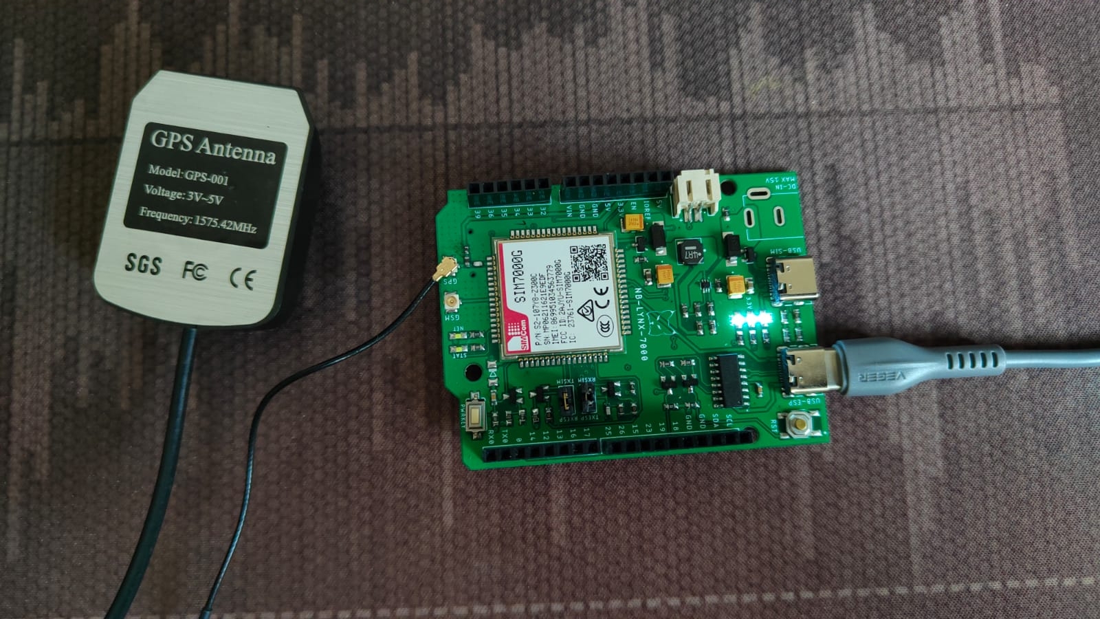
The first thing you need to do is to setup the equipment by connecting the NB-LYNX-7000 board with the GPS Antenna. The board can then be connected to your laptop/computer using a USB-C cable.

You need to connect the GPS Antenna to the GPS antenna port located on the NB-LYNX-7000 board.

Here are the equipment circuits that have been connected to a laptop/computer.
2. Launch Arduino IDE

3. Inputting programme code

To retrieve GNSS data, you need to input the programme code below in the Arduino IDE.

#include <Arduino.h>

// Configurable macros
#define SIM7000_POWER_KEY 27

String sendCommand(String command, uint32_t timeout, char delimiter)
{
 while (Serial2.available())
  Serial2.read();

 uint32_t T = millis();
 String res = "";
 Serial.print("[SYS CMD] ");
 Serial.print(command);
 Serial.println("=========");
 Serial2.print(command);
 while ((millis() - T) < timeout)
 {
  while (Serial2.available())
  {
   res = Serial2.readStringUntil(delimiter);
   res.trim();
   if (res.length() > 0)
   {
    Serial.print("[SYS RES] ");
    Serial.println(res);
    return res;
   }
  }
 }
 return "TIMEOUT";
}

String receiveAddCommand(int32_t timeout)
{
 String res = "";
 uint32_t T = millis();
 while ((millis() - T) < timeout)
 {
  while (Serial2.available())
  {
   res = Serial2.readStringUntil('\0');
   res.trim();
   if (res.length() > 0)
   {
    Serial.print("[SYS RES] ");
    Serial.println(res);
    return res;
   }
  }
 }
 return res;
}

bool checkResponse(String response, String expected_response)
{
 if (response.indexOf(expected_response) != -1)
  return true;
 else
  return false;
}

bool sim7000_powerOn()
{
 pinMode(SIM7000_POWER_KEY, OUTPUT);
 delay(100);
 digitalWrite(SIM7000_POWER_KEY, LOW);
 delay(1000);
 digitalWrite(SIM7000_POWER_KEY, HIGH);
 delay(1000);
 for (uint8_t i = 0; i < 5; i++)
 {
  String response = sendCommand("AT\r\n", 200, '\n');
  if (checkResponse(response, "AT"))
  {
   sendCommand("ATE0\r\n", 200, '\n');
  }
  else if (checkResponse(response, "OK"))
  {
   return true;
  }

  delay(1000);
 }
 return false;
}

bool sim7000_powerOnGNSS()
{
 if (!checkResponse(sendCommand("AT+CGNSPWR=1\r\n", 200, '\n'), "OK"))
  return false;
 if (!checkResponse(sendCommand("AT+CGNSURC=1\r\n", 200, '\n'), "OK"))
  return false;

 return true;
}

void sim7000_parseGNSS(String input)
{
 // Serial.println(input);
 int firstCommaIndex = input.indexOf(",");
 int secondCommaIndex = input.indexOf(",", firstCommaIndex + 1);
 int thirdCommaIndex = input.indexOf(",", secondCommaIndex + 1);
 int fourthCommaIndex = input.indexOf(",", thirdCommaIndex + 1);
 int fifthCommaIndex = input.indexOf(",", fourthCommaIndex + 1);
 int sixthCommaIndex = input.indexOf(",", fifthCommaIndex + 1);

 int isGnssRun = input.substring(0, firstCommaIndex).toInt();
 if (isGnssRun == 0)
 {
  Serial.println("[SIM7000] GNSS is not running");
  return;
 }
 
 int isGnssFix = input.substring(firstCommaIndex + 1, secondCommaIndex).toInt();
 if (isGnssFix == 0)
 {
  Serial.println("[SIM7000] GNSS is not fixed");
  return;
 }

 Serial.print("Latitude : ");
 Serial.println(input.substring(thirdCommaIndex + 1, fourthCommaIndex));
 Serial.print("Longitude : ");
 Serial.println(input.substring(fourthCommaIndex + 1, fifthCommaIndex));
 Serial.print("Altitude : ");
 Serial.println(input.substring(fifthCommaIndex + 1, sixthCommaIndex));

 Serial.print("Date & Time : ");
 String datetime = input.substring(secondCommaIndex + 1, thirdCommaIndex);
 Serial.print(datetime.substring(6, 8));
 Serial.print("/");
 Serial.print(datetime.substring(4, 6));
 Serial.print("/");
 Serial.print(datetime.substring(0, 4));
 Serial.print(" ");
 Serial.print(datetime.substring(8, 10));
 Serial.print(":");
 Serial.print(datetime.substring(10, 12));
 Serial.print(":");
 Serial.print(datetime.substring(12, 14));
 Serial.print("\n");
}

bool gnssSetup()
{
 Serial2.begin(9600);
 Serial2.flush();
 Serial.println("[SIM7000] Turning ON...");
 if (sim7000_powerOn())
  Serial.println("Success");
 else
 {
  Serial.println("Failed");
  Serial.println("Hold PWRKEY for 3 seconds and press RST");
  return false;
 }

 Serial.println("[SIM7000] Turning ON GNSS...");
 if (sim7000_powerOnGNSS())
  Serial.println("Success");
 else
 {
  Serial.println("Failed");
  return false;
 }

 return true;
}

void setup()
{
 Serial.begin(115200);
 if (!gnssSetup())
 {
  while (1)
   delay(1000);
 }
}

void loop()
{
 String res = "";
 while (Serial2.available())
 {
  res = Serial2.readStringUntil('\0');
  res.trim();
  if (checkResponse(res, "+UGNSINF:"))
  {
   res.replace("+UGNSINF:","");
   sim7000_parseGNSS(res);
  }
 }
}

4. Programme Code Explanation

In order for the NB-LYNX-7000 board to communicate with the Antares platform, a SIM7000 module is used. SIM7000 is a cellular communication module developed by SIMCom Wireless Solutions. This module implements several protocols that allow the device to connect to the network using AT commands. The following describes some of the AT commands used in the programme code.

AT<CR><LF>

In the program code, the command "AT\r\n" is sent as the starting point or initialisation stage of the SIM7000 module. \r is a carriage return, while \n is a line feed. This command is sent to get an "OK" response.

ATE0<CR><LF>

In the programme code there is an "ATE0\r\n" command sent after getting an "OK" response. This command is used to disable echo mode indicating that initialisation has been successful.

AT+CGNSPWR=<mode><CR><LF>

In the programme code there is a command "AT+CGNSPWR=1\r\n" which is used to power control the GNSS module. Parameter "1" is used to switch on the GNSS power supply.

Here are other parameters that can be used.

  • 0 = Switching off the GNSS power supply

  • 1 = Switching on the GNSS power supply

AT+CGNSURC=<Navigation mode><CR><LF>

In the programme code there is a command "AT+CGNSURC=1\r\n" which is used to display navigation data. Parameter "1" is used to display navigation data every time GNSS receives a signal from the satellite.

Here are some other parameters that can be used

  • 0 = Turn off the displayed navigation data

  • 1 = Displays navigational data every time the GNSS receives a signal

  • 2 = Displays navigation data once every time the GNSS has received a signal for 2 times

  • …

  • 256 = Displays navigation data once every time the GNSS has received a signal 256 times

5. Program Upload to NB-LYNX-7000 Board

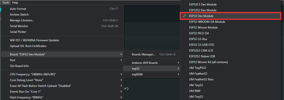
Firstly, you must set up the board used by selecting ESP32 Dev Module under Tools > Board > esp32.
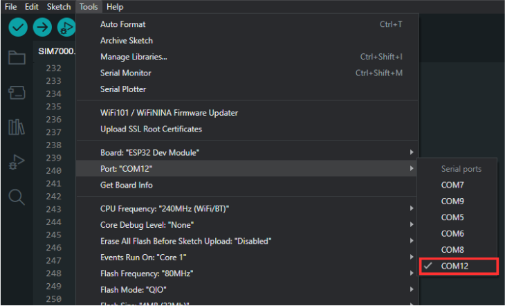
After that, you need to set the port used by going to Tools > Port > COM(X). The X value corresponds to the port number used by the NB-LYNX-7000 board.
After you have prepared the programme code, you can then upload the programme code by pressing the upload button as shown in the image below.

If the programme code has been uploaded successfully, you can open the Serial Monitor by pressing the icon as shown in the image below. You can find the icon on the top right-hand side.

You need to set the Serial Monitor's baud rate to 115200 so that its output can be read.

The Serial Monitor display will be as shown below which signifies the SIM7000 module initiation process and the process of turning on the GNSS to get navigation data.

Furthermore, the GPS Antenna will work to receive signals from satellites to obtain GNSS data in the form of navigation information consisting of latitude, longtitude, altitude, and date & time.

GPS Antenna sometimes takes a long time to receive signals from satellites until GNSS data is finally received. In this case, you can wait for a while.

If you have waited for a while but have not received GNSS data, it is likely that the GPS Antenna is not receiving enough signals from the satellites.

When the GPS Antenna is not receiving enough signals from the satellites, the display on the serial monitor will be as shown below.
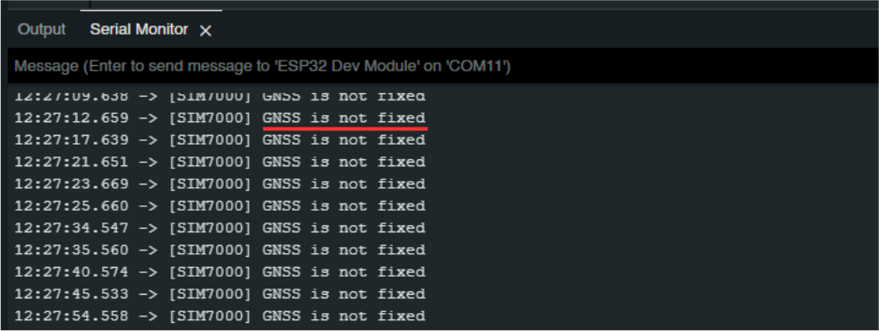
If the GPS Antenna is not receiving enough signal from the satellites, you can bring the GPS Antenna to an open room or by bringing it closer to a window.

When the antenna has received enough signal, the GNSS data will be displayed on the serial monitor as shown below.
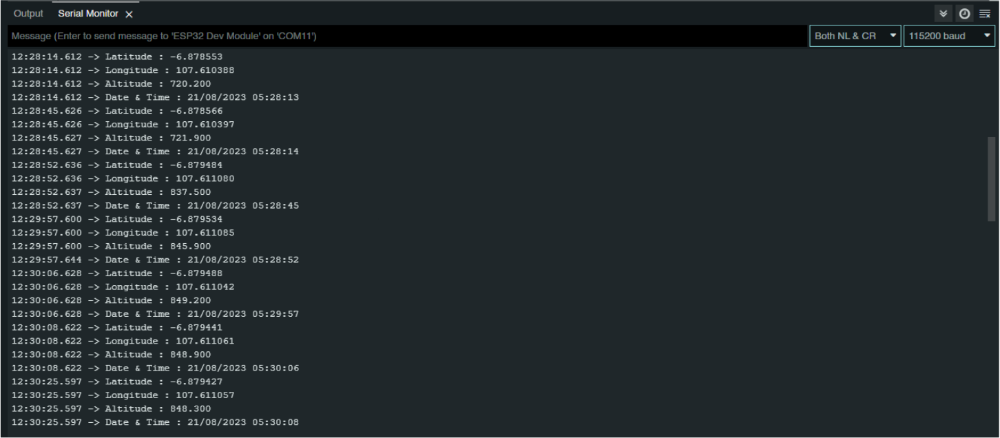
In this condition, the GPS Antenna will continuously receive signals from the satellite to display GNSS data on the serial monitor.

General Prerequisites NB-Lynx-7000
NB-LYNX-7000 Connected with GPS Antenna
Board Selection
Port Selection
Upload programme code
Serial Monitor Icon
Baud Rate
Serial Monitor Output Showing the Process of Initiating the SIM7000 Module and Turning on the GNSS
Monitor Serial Output When the Antenna is Not Receiving Enough Signal
Serial Monitor output when successfully receiving GNSS data