Retrieve Last Data from Antares Server with MQTT Protocol
Prerequisites
General Prerequisites ESP32 Wi-FiFollow These Steps
1. Run the Arduino IDE application
2. Opening Sample Programme
/*
    This is an example sketch to subscribe to MQTT data on ESP8266
    via the Antares IoT Platform.

    MQTT server & port:
    platform.antares.id, port 1338

    MQTT topic:
    /oneM2M/req/your-access-key/antares-cse/json

    The main function in this sketch is the callback function,
    which will be fired every time a new message is published
    to the topic.

    For more information, please visit https://antares.id/id/docs.html
*/

#include <AntaresESPMQTT.h>

#define ACCESSKEY "YOUR-ACCESS-KEY"       // Antares account access key
#define WIFISSID "YOUR-WIFI-SSID"         // Wi-Fi SSID to connect to
#define PASSWORD "YOUR-WIFI-PASSWORD"     // Wi-Fi password

#define projectName "YOUR-APPLICATION-NAME"   // Name of the application created in Antares
#define deviceName "YOUR-DEVICE-NAME"     // Name of the device created in Antares

AntaresESPMQTT antares(ACCESSKEY);

unsigned long previousMillis=0;
unsigned long interval =5000;

void callback(char topic[], byte payload[], unsigned int length) {
  /*
    Get the whole received data, including the topic,
    and parse the data according to the Antares data format.
  */
  antares.get(topic, payload, length);

  Serial.println("New Message!");
  // Print topic and payload
  Serial.println("Topic: " + antares.getTopic());
  Serial.println("Payload: " + antares.getPayload());
  // Print individual data
}

void setup() {
  Serial.begin(115200);
  antares.setDebug(true);
  antares.wifiConnection(WIFISSID, PASSWORD);
  antares.setMqttServer();
  antares.setCallback(callback);
}
void loop() {
  /*
    Check if we're still connected to the MQTT broker/server.
    If disconnected, the device will try to reconnect.
  */
  antares.checkMqttConnection();

  while(millis()-previousMillis > interval)
  {
    previousMillis = millis();
    antares.retrieveLastData(projectName,deviceName);
  }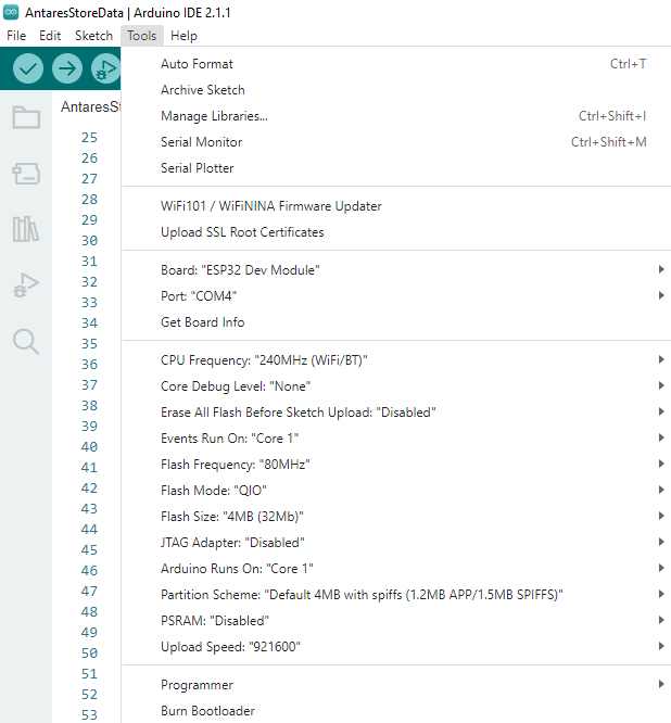
}3. Set MQTT Parameters in Programme Code


4. Compile and Upload Program


5. Check Data in Antares


PreviousSending Simple Data to Antares with the MQTT ProtocolNextSimple Project Lynx-32 MQTT Antares
Last updated