Sending Simple Data to Antares
In this project you will be directed to send simple data from the NB-LYNX-95 board to the Antares IoT Platform using a series of AT Commands from the BG95-M3 module.
Prerequisites
The materials required follow the General Prerequisites on the previous page. If you have not prepared the requirements on that page, then you can visit the following page.
General Prerequisites NB-Lynx-95Follow These Steps
1. Equipment Setup
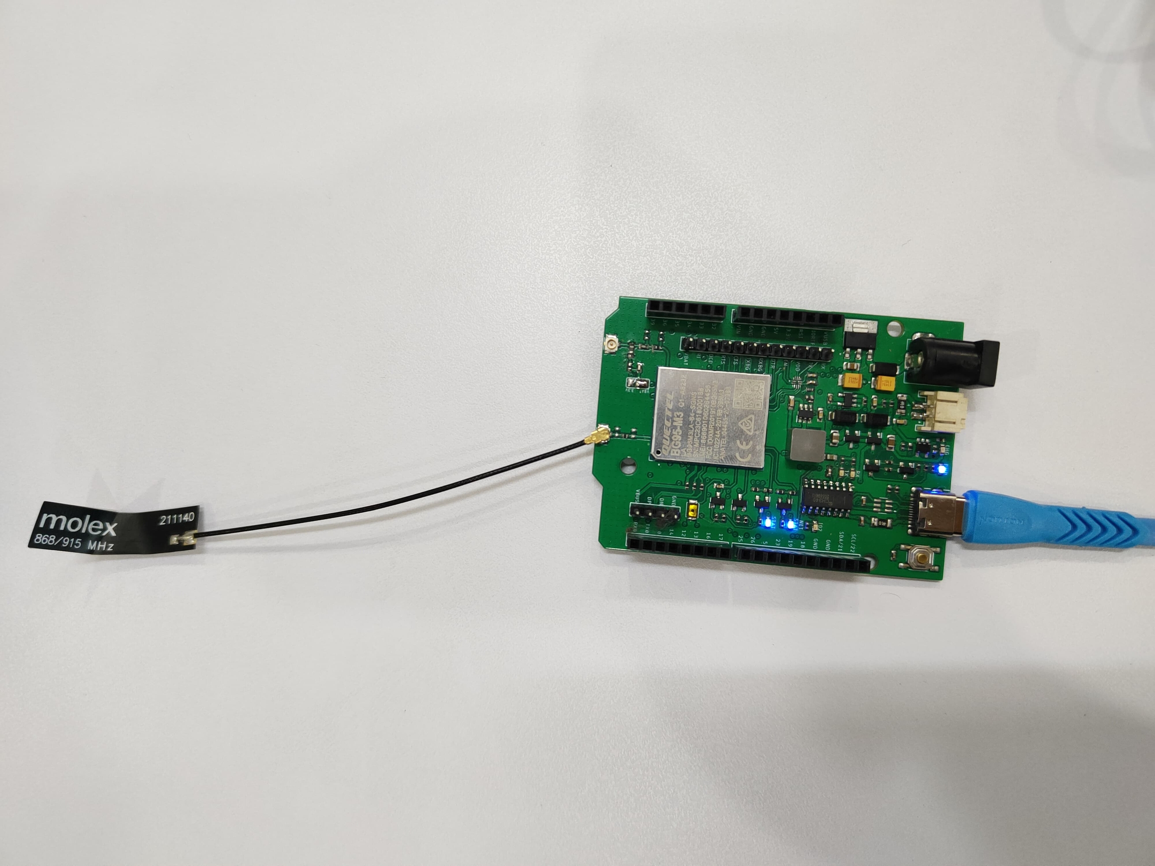
The first thing you need to do is to setup the equipment by connecting the NB-LYNX-95 board to your laptop/computer device using a USB-C cable.
Make sure you have installed the antenna on the GSM antenna port before connecting the NB-LYNX-95 board to your laptop/computer.
Here is the NB-LYNX-95 board connected to a laptop/computer.
2. Launch the Arduino IDE application
3. Inputting programme code
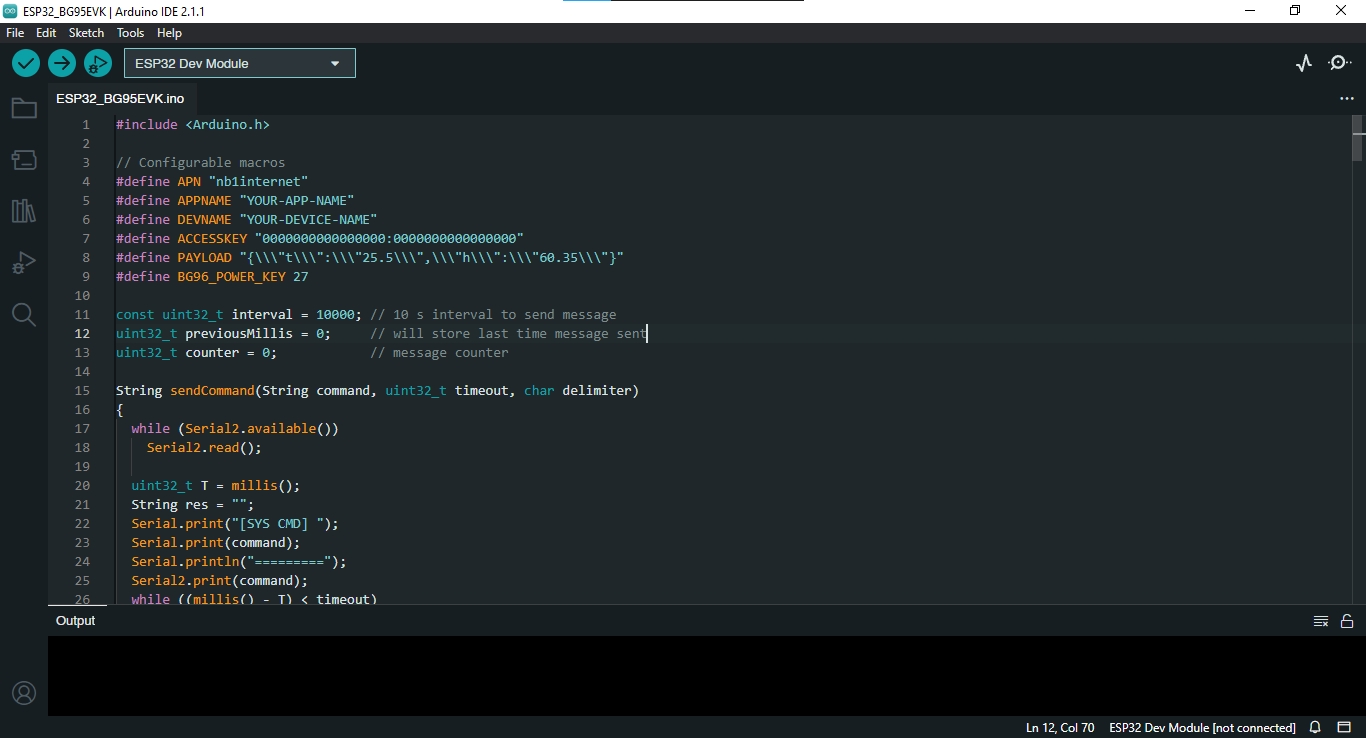
To send data to Antares, you need to input the programme code below in the Arduino IDE.
Don't forget to replace APPNAME with the name of the application you created on the Antares platform, DEVNAME with the name of the device created on the Antares platform, and ACCESSKEY with your account access-key.
After inputting the programme code, don't forget to save the programme code by selecting File > Save As. Here is how the Arduino IDE looks when you have inputted the code.
4. Programme Code Explanation
In order for the NB-LYNX-95 board to communicate with the Antares platform, the BG95-M3 module is used. BG95-M3 is a cellular communication module developed by Quectel. This module implements several protocols that allow the device to connect to the internet network using AT commands. The following describes some of the AT commands used in the programme code.
In the program code, the command "AT\r\n" is sent as the starting point or initialisation stage of the SIM7000 module. \r is a carriage return, while \n is a line feed. This command is sent to get an "OK" response.
In the programme code there is an "ATE0\r\n" command sent after getting an "OK" response. This command is used to disable echo mode indicating that initialisation has been successful.
In the programme code, the command "AT+QCFG="nwscanseq",03,1\r\n" is sent to set the RAT (Radio Access Technology) search order. In the command there is a parameter "03" which is as the search order for NB-IoT, while the parameter "1" is so that the configuration takes effect immediately.
Here are other parameters that can be used
00 = Otomatis (eMTC --> NB-IoT --> GSM)
01 = GSM
02 = eMTC
03 = NB-IoT
Here's another parameter that can be used
0 = Configuration takes effect when UE (user equipment) is restarted
1 = Configuration will take effect immediately
In the programme code, the command "AT+QCFG="nwscanmode",3,1\r\n" is sent to determine the RATs that can be searched. Parameter "3" is the to search on LTE only, while parameter "1" is for the configuration to take effect immediately.
Berikut parameter lengkap <scanmode> yang dapat digunakan
0 = Otomatis
1 = GSM saja
3 = LTE saja
In the programme code there is a command "AT+QCFG="iotopmode",1,1\r\n" which is sent to determine the network category to be searched under LTE RAT. The "1" parameter is to search for network categories in the form of NB-IoT, while the next "1" parameter is so that the configuration takes effect immediately.
Here are the full parameters that can be used
0 = eMTC
1 = NB-IoT
2 = eMTC dan NB-IoT
In the programme code there is a command "AT+QCFG="band",3,80,80,1\r\n" which is sent to determine the frequency band that is allowed to be searched. Parameter "3" is to set the GSM frequency in Indonesia which is at 900 MHz and 1800 MHz, parameter "80" is to set the frequency on LTE B8, while the next parameter "80" is to set the NB-IoT frequency on LTE B8, then parameter "1" is so that the configuration takes effect immediately.
In the program code, the command "AT+QCFG="servicedomain",1,1\r\n" is sent to specify the registered service domain. Parameter "1" is to specify the service domain as PS (Packet Swithced) only, while the next parameter "1" is so that the configuration takes effect immediately.
Here are the full parameters that can be used
1 = PS (Packet Swithced ) saja
2 = CS (Circuit Switched) dan PS (Packet Swithced)
In the programme code, the command "AT+QIDEACT=1\r\n" is sent to disable the PDP context, in this case set on the parameter with the value "1", and close all TCP/IP connections.
In the programme code there is a command "AT+QICSGP=1,1,"" + String(APN) + "","","",0\r\n" to set the TCP/IP context parameters , , , and . Parameter "1" indicates the value of , while the next parameter "1" indicates the value of <context_type> to set the protocol used as IPv4.
In the command, the parameter is set with String(APN) as defined at the beginning of the programme with the value "nb1internet". For other parameters such as and are left empty in this command, while for the parameter is set as "0" which indicates that no authentication method is used.
Here are the full <context_type> parameters that can be used
1 = IPv4
2 = IPv6
3 = IPv4v6
Here are the full parameters that can be used
0 = No authentication
1 = PAP
2 = CHAP
3 = PAP or CHAP
In the programme code, the command "AT+QIACT=1\r\n" is sent to activate the PDP context with the value is "1".
In the programme code, the command "AT+QIACT?\r\n" is sent to display the active PDP context along with the IP address.
In the programme code there is a command "AT+QIOPEN=1,0, "TCP", "platform.antares.id",8080\r\n" which is sent to open the socket service, in this case the Antares IoT Platform. Parameter "1" is , while parameter "0" is . Furthermore, the parameter "TCP" is also defined as <service_type>, "platform.antares.id" as the <domain_name> of the Antares IoT Platform, while the parameter "8080" as the <remote_port> of the remote server.
In the programme code there is a command "AT+QISEND=0\r\n" which is sent to send data to the socket service that has been previously set. Parameter "0" is the value of .
In the programme code there is a command "AT+QICLOSE=0\r\n" which is sent to close the running socket service. Parameter "0" is the value of .
5.Program Upload to NB-LYNX-7000 Board
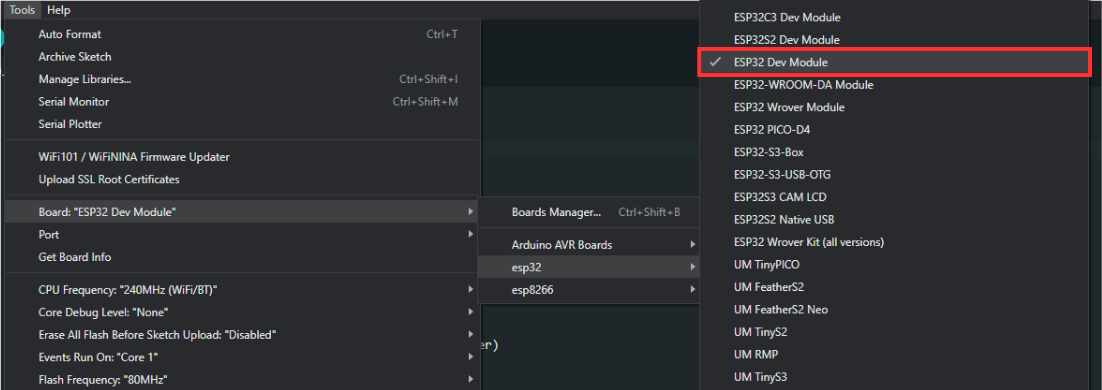
Firstly. You must set up the board being used by selecting ESP32 Dev Module under Tools > Board > esp32.
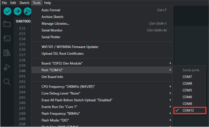
After that, you need to set the port used by going to Tools > Port > COM(X). The X value corresponds to the port number used by the NB-LYNX-7000 board.
After you have prepared the programme code, you can then upload the programme code by pressing the upload button as shown in the image below.

If the programme code has been uploaded successfully, you can open the Serial Monitor by pressing the icon as shown in the image below. You can find the icon on the top right-hand side.

You need to set the Serial Monitor's baud rate to 115200 so that its output can be read.

The Serial Monitor display will be as shown below, signalling the initiation of the BG95-M3 module.

The next process that will occur in the serial monitor is setting the mode to NB-IoT with LTE network. The following display appears on the serial monitor.

After success, the process that works is setting up network connectivity by starting an IP connection. Here is the display that appears on the serial monitor.

After the IP is successfully obtained, the NB-LYNX-95 module is ready to send data to the Antares IoT Platform. The process of sending data is marked with the words "Sending frame" which starts from frame 0. Then the module will access the Antares server with a TCP connection to send data. The following is the display on the serial monitor.
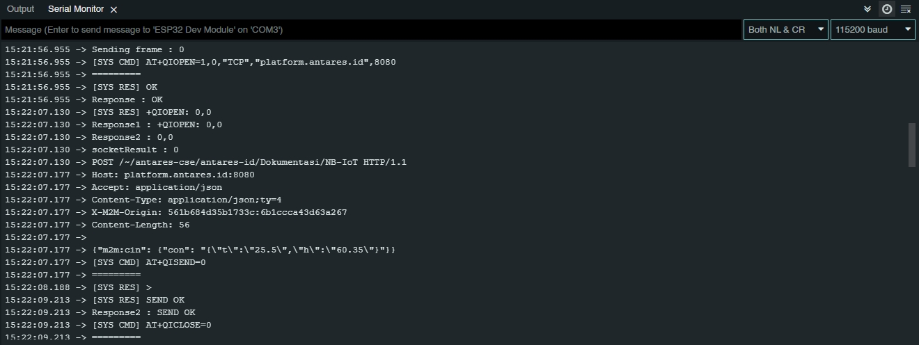
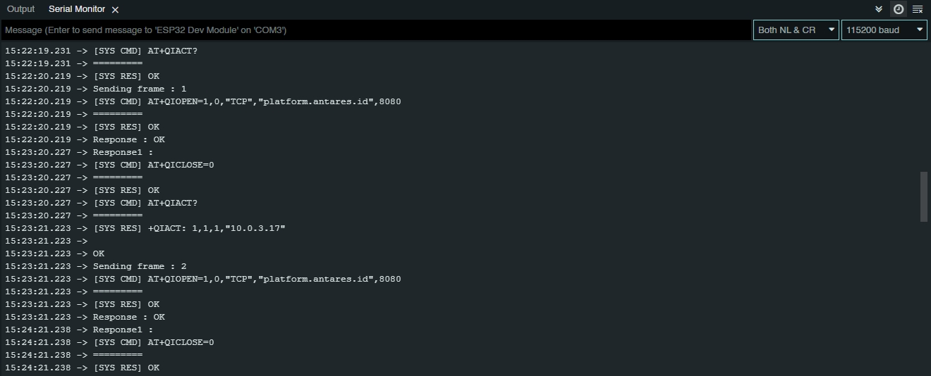
In the figure above, the NB-LYNX-95 module has successfully sent one data to the Antares IoT Platform. The programme code is designed to continuously send data to the Antares IoT Platform as indicated by the frame count. Here is the display on the serial monitor when sending the next data.
6. Check Data on Antares IoT Platform
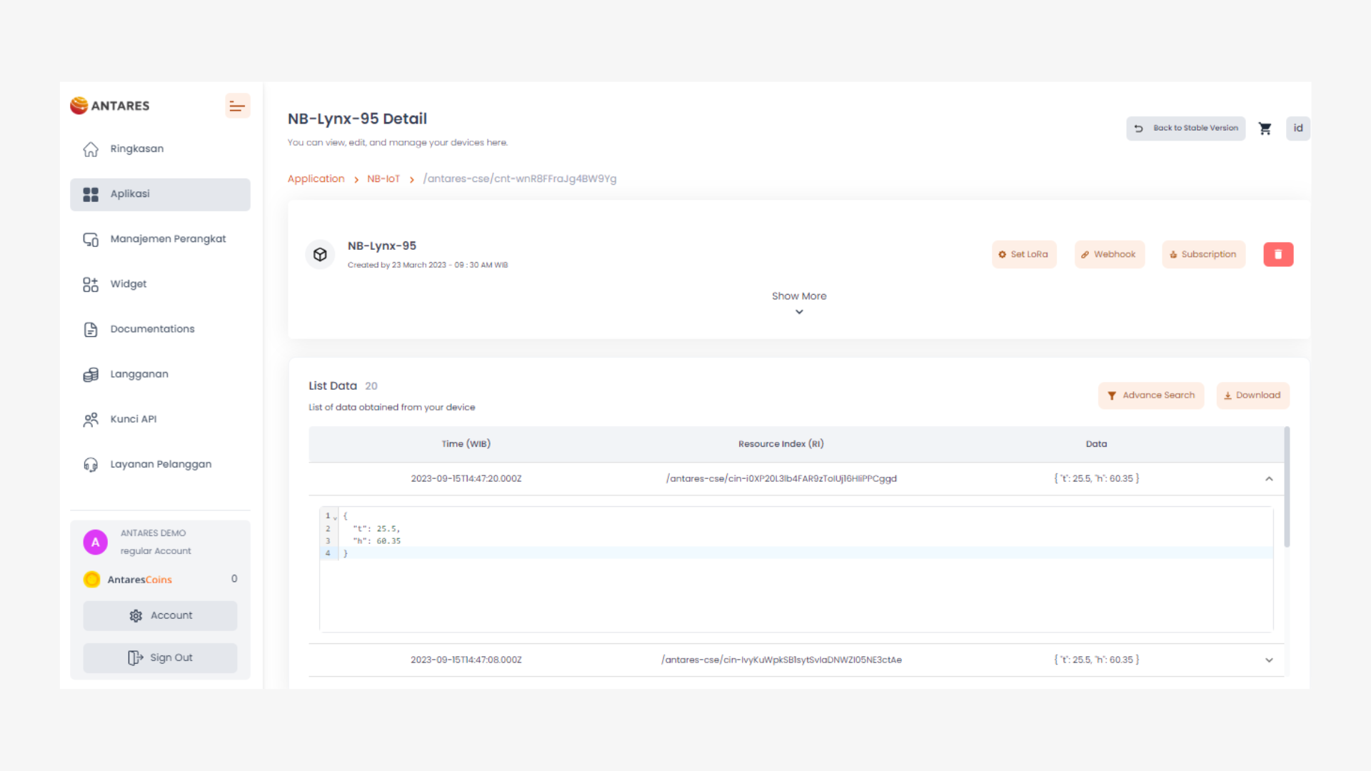
To ensure that data has been sent correctly from the NB-LYNX-95 module to the Antares IoT Platform, you can open your device's URL. The following figure shows the display on the Antares IoT Platform that has received data from the NB-LYNX-7000.
Last updated