Sending Simple Data to Antares
In this project you will be directed to send dummy data from the Lynx-32 Development Board to the Antares IoT Platform using LoRa connectivity with the LoRaWAN protocol.
The LoRaWAN protocol is divided into two classes, Class A and Class C, each class has its own advantages and disadvantages, for more details please visit the following page.
LoRaWAN ClassPrerequisites
The required materials follow the General Prerequisites on the previous page. If you have not prepared the requirements on that page, then you can visit the following page.
General Prerequisites ESP32 LoRaFollow These Steps
1. Launch the Arduino IDE application
2. Opening Sample Programme
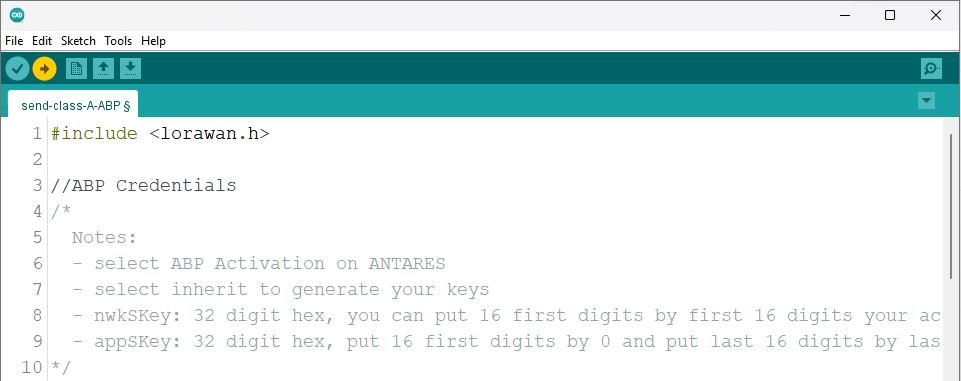
You can open the programme code in the Arduino IDE viaFile > Examples > Antares LoRaWAN > send-class-A-ABP.
Here is the programme code of the send-class-A-ABP example.
3. Set LoRaWAN Parameters in Antares
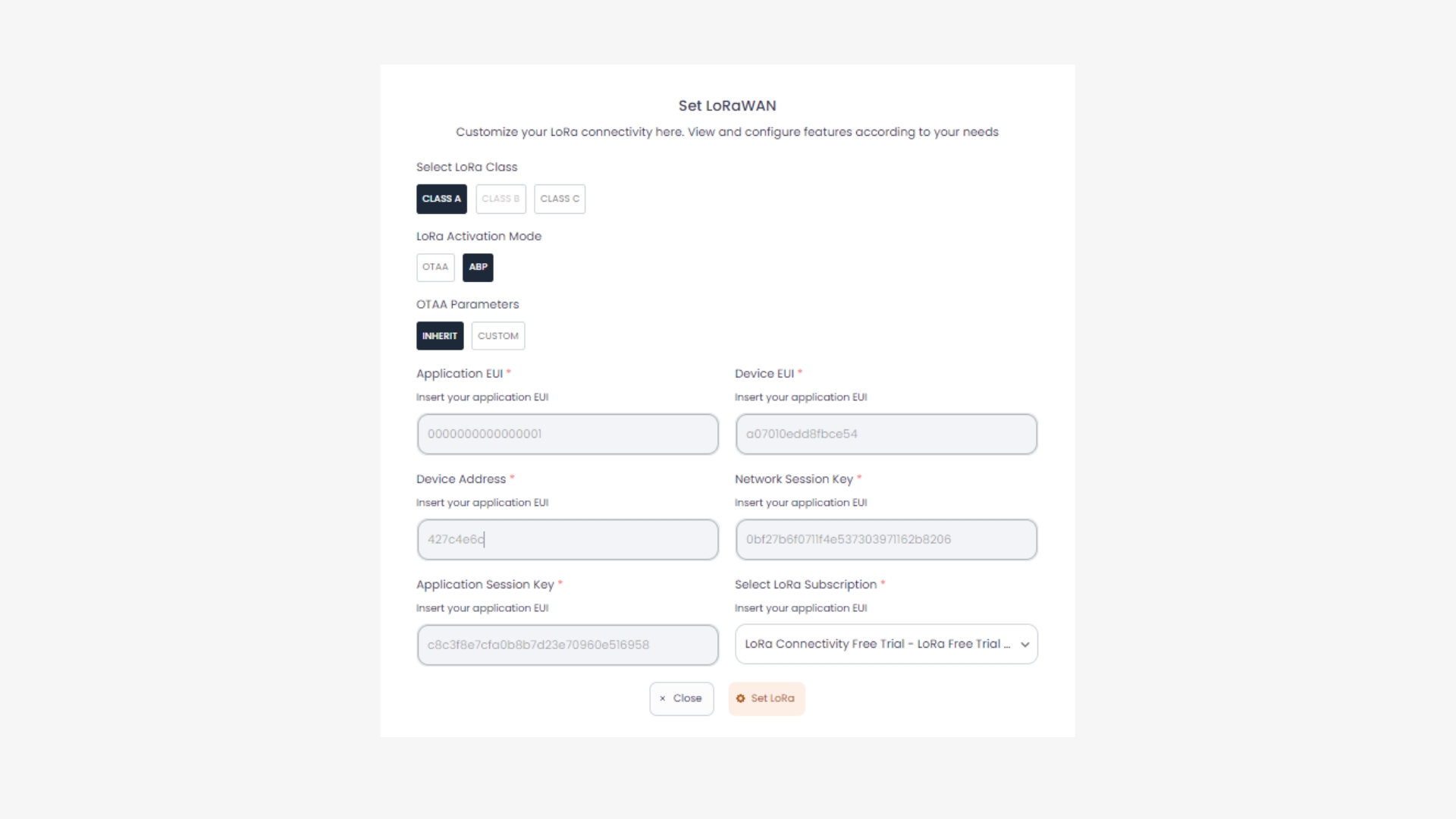
On the Antares Device console page, set LoRa by pressing the Set LoRa button as shown below.
Input LoRaWAN parameters with Lora Device Class A, Activation Mode ABP, ABP Parameters Inherit as shown below.
When selecting ABP Parameters Inherit, the LoRa parameters will be generated by Antares. From the device side, the Lynx32 Development Board needs to adjust the LoRa parameters.
Don't forget to save (copy) the Network Session Key and Application Session Key parameters before clicking Set LoRa to facilitate the next process.
Make sure your antares account has an active LoRa package.
4. Set LoRaWAN Parameters in the Programme Code
Change the LoRaWAN ABP parameters in the following variables *devAddr , *nwkSkey , and *appSKey. Adjust to the parameters in the Antares console.
The *devAddr parameter that has been generated by Antares can be seen on the device page after completing the LoRa Set.
The parameters *nwkSKey and *appSKey are obtained during Set LoRa in the previous step.
If you forgot to save *nwkSkey and *appSKey in the previous step then look at the accesskey in your antares account then follow the following format.
5. Compile and Upload Program
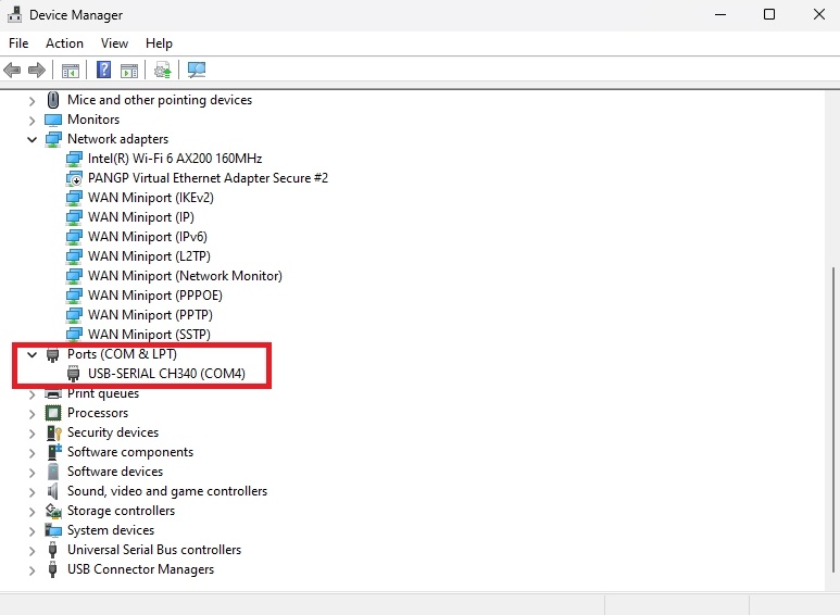
Connect the Lynx-32 Development Board to your computer and make sure the Communication Port is read.
On Windows operating systems, checking can be done through the Device Manager. If your Lynx-32 Development Board is read, the USB-Serial CH340 will appear with the port adjusting the port availability (in this case it reads COM4).
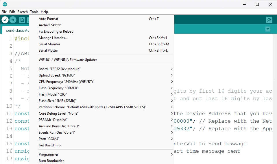
Set up the Lynx-32 Board by clicking Tools > Board > ESP32 Arduino in the Arduino IDE, then make sure the board used is the ESP32 Dev Module. Select the port according to the communicaion port that is read (in this case COM4). The result will look like the following picture.
After all the setup is complete, upload the programme by pressing the arrow icon as shown below. Wait for the compile and upload process to finish.
The Tick icon on the Arduino IDE is just the verify process. Usually used to Compile the programme to find out whether there are errors or not. The Arrow icon on the Arduino IDE is the verify and upload process. Usually used to Compile the programme as well as Flash the programme to the target board.
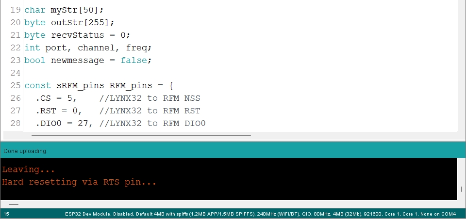
If the programme upload is successful, it will look like the following image.
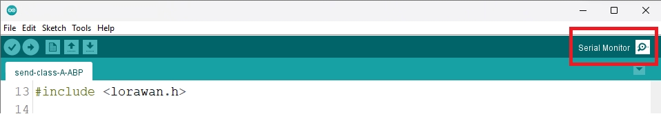
After uploading the programme, you can view the serial monitor to debug the programme. The serial monitor icon is shown in the following image.
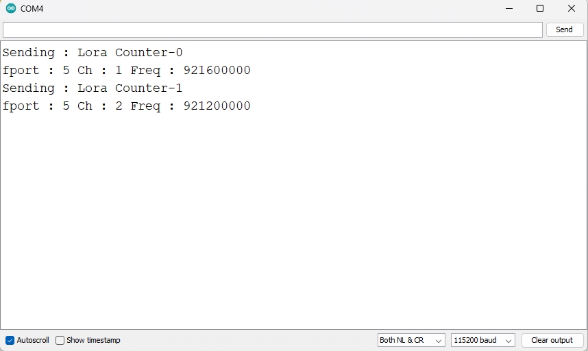
Set the serial baud rate to 115200 and select BothNL & CR. The result will look like the following image.
Make sure the serial baud rate matches the value defined in the programme code. If the serial baud rate is not the same between the programme code and the serial monitor, the ASCII characters will not be read properly.
6. Check Data in Antares
After uploading the programme successfully, then open the device antares page and see if the lora data has been successfully sent.
The data sent from the Lynx-32 Development Board is in the form of "counter", "port", and message in the JSON field "data". While other parameters are supporting parameters generated by the Antares LoRaWAN Infrastructure.
Last updated