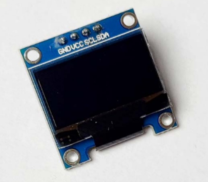
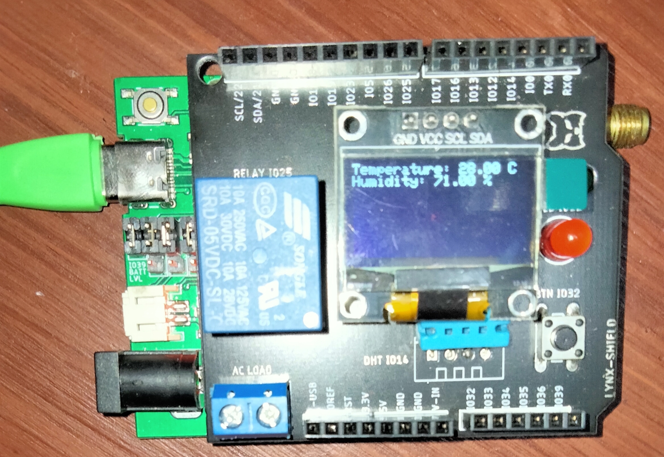
In this project, you will use the Antares Workshop Shield on the Lynx-32 Development Board module. In this Antares Shield Workshop, there are temperature, humidity (DHT11), relay, LED and push button sensors. You will monitor the temperature and humidity according to the specified interval period. The results of the data sent by the sensors can be monitored through the Antares console and displayed on the OLED.
Prerequisites
The materials required follow the General Prerequisites on the previous page. If you have not prepared the requirements on that page, then you can visit the following page.
The additional materials specific to this project are as follows.
You can open the programme code in the Arduino IDE via File > Examples > Antares ESP HTTP > Lynx32-Simple-Project > POST_DATA_DHT11_OLED.
The following is the POST_DATA_DHT11_OLED example programme code.
// Library initialization
#include <AntaresESPHTTP.h>   // Load AntaresESP32HTTP library for connecting to the Antares platform
#include "DHT.h"               // Load DHT sensor library for reading temperature and humidity
#include <Adafruit_SSD1306.h>  // Load OLED display library

#define DHTPIN 14            // Define DHTPIN variable, pointing to pin 14
#define DHTTYPE DHT11        // Set DHT type to DHT11
#define SCREEN_WIDTH 128     // Define OLED screen width
#define SCREEN_HEIGHT 64     // Define OLED screen height

#define OLED_RESET -1        // Define OLED reset pin, set to -1 as it's not used
#define SCREEN_ADDRESS 0x3C  // Define OLED I2C address

#define ACCESSKEY "YOUR-ACCESS-KEY"       // Replace with your Antares account access key
#define WIFISSID "YOUR-WIFI-SSID"         // Replace with your Wi-Fi SSID
#define PASSWORD "YOUR-WIFI-PASSWORD"     // Replace with your Wi-Fi password

#define projectName "YOUR-APPLICATION-NAME"   // Replace with the Antares application name that was created
#define deviceName "YOUR-DEVICE-NAME"     // Replace with the Antares device name that was created

const unsigned long interval = 10000;    // 10 s interval to send message
unsigned long previousMillis = 0;  // will store last time message sent

AntaresESPHTTP antares(ACCESSKEY);   // Create an antares object for connecting to Antares
DHT dht(DHTPIN, DHTTYPE);             // Create a dht object for the DHT sensor
Adafruit_SSD1306 display(SCREEN_WIDTH, SCREEN_HEIGHT, &Wire, OLED_RESET);  // Create a display object for the OLED screen

void setup() {
  Serial.begin(115200);     // Initialize serial communication with baudrate 115200
  antares.setDebug(true);   // Turn on debug mode. Set to "false" if you don't want messages to appear in the serial monitor

  // Reset WiFi cache before connecting
  WiFi.disconnect();

  antares.wifiConnection(WIFISSID, PASSWORD);  // Attempt to connect to Wi-Fi with the specified SSID and password
  dht.begin();             // Initialize the DHT sensor object

  if (!display.begin(SSD1306_SWITCHCAPVCC, SCREEN_ADDRESS)) {
    Serial.println(F("SSD1306 allocation failed"));   // Check if the OLED is successfully initialized
    for (;;);
  }
  display.clearDisplay();   // Clear the OLED display
  display.setTextColor(SSD1306_WHITE);   // Set text color to white
  display.setTextSize(1);   // Set text size to 1
  display.setCursor(0, 0);   // Set cursor position to (0, 0)
  display.println(F("Temperature & Humidity"));   // Display "Temperature & Humidity" text on the OLED
  display.display();         // Show the text on the OLED
  delay(2000);               // Delay for 2 seconds
}

void loop() {

  // Check interval overflow
  if (millis() - previousMillis > interval) {
  previousMillis = millis();

  float hum = dht.readHumidity();      // Read humidity value from the DHT sensor
  float temp = dht.readTemperature();  // Read temperature value from the DHT sensor
  if (isnan(hum) || isnan(temp)) {     // Check if the sensor reading is invalid
    Serial.println("Failed to read DHT sensor!");   // If the reading is invalid, print an error message
    return;   // Exit the loop function and wait for the next cycle
  }
  display.clearDisplay();   // Clear the OLED display
  display.setTextSize(1);   // Set text size to 1
  display.setCursor(0, 0);   // Set cursor position to (0, 0)
  display.print(F("Temperature: "));   // Display "Temperature: " text on the OLED
  display.print(temp);         // Display temperature value on the OLED
  display.println(F(" C"));    // Display " C" (for Celsius) on the OLED
  display.print(F("Humidity: "));   // Display "Humidity: " text on the OLED
  display.print(hum);          // Display humidity value on the OLED
  display.println(F(" %"));    // Display " %" (for percentage) on the OLED
  display.display();          // Show the text on the OLED

  Serial.println("Temperature: " + (String)temp + " *C");  // Print temperature value to the serial monitor with "*C" format
  Serial.println("Humidity: " + (String)hum + " %");       // Print humidity value to the serial monitor with "%" format

  // Add variable data to the storage buffer in Antares
  antares.add("temperature", temp);
  antares.add("humidity", hum);

  // Send data from the storage buffer to Antares
  antares.send(projectName, deviceName);

  }
}
3. Set HTTP Parameters in Programme Code
Change the HTTP Protocol parameters in the following variables *ACCESSKEY, *WIFISSID, *PASSWORD, *projectName, and *deviceName. Adjust to the parameters in the Antares console.
#define ACCESSKEY "YOUR-ACCESS-KEY"       // Replace with your Antares account access key
#define WIFISSID "YOUR-WIFI-SSID"         // Replace with your Wi-Fi SSID
#define PASSWORD "YOUR-WIFI-PASSWORD"     // Replace with your Wi-Fi password

#define projectName "YOUR-APPLICATION-NAME"   // Replace with the Antares application name that was created
#define deviceName "YOUR-DEVICE-NAME"     // Replace with the Antares device name that was created
The *Access key parameter is obtained from your Antares account page.
The WIFISSID parameter is obtained from the name of the Wifi / Hotspot that is currently being used by you. for example in the image below.
The *PASSWORD parameter is obtained from the WiFi password you are currently using.
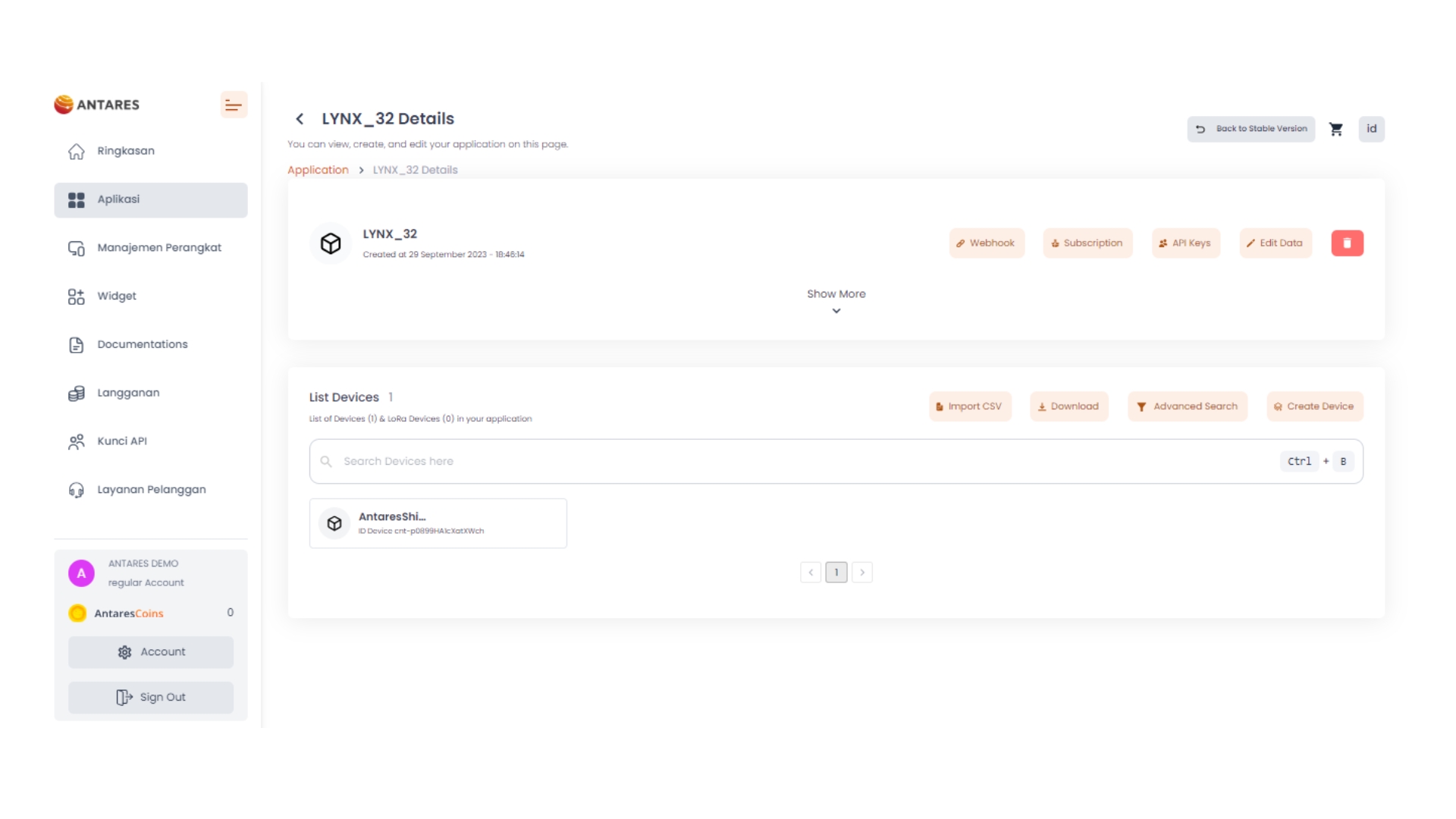
The parameters *projectName and *deviceName are obtained from the Application Name and Device Name that have been created in the Antares account.
4. Compile and Upload Program
Connect the Lynx-32 with your computer and make sure the Communication Port is read.
On Windows operating systems, checking can be done via Device Manager. If your ESP8266 WEMOS D1R2 is read, the USB-Serial CH340 appears with the port adjusting the port availability (in this case it reads COM4).
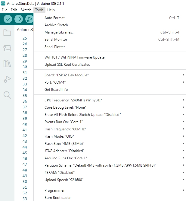
Set up the ESP32 board by clicking Tools > Board > esp32 in the Arduino IDE, then make sure the ESP32 Dev Module is used. Select the port according to the communication port that is read (in this case COM4). The result will look like the following image.
After all the setup is complete, upload the programme by pressing the arrow icon as shown below. Wait for the compile and upload process to finish.
The Tick icon on the Arduino IDE is just the verify process. Usually used to Compile the programme to find out whether there are errors or not.
The Arrow icon on the Arduino IDE is the verify and upload process. Usually used to Compile the programme as well as Flash the programme to the target board.
If the programme upload is successful, it will look like the following image.
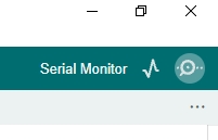
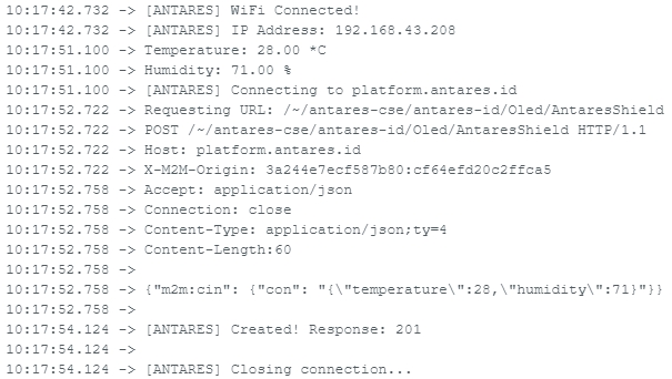
After uploading the programme, you can view the serial monitor to debug the programme. The serial monitor icon is shown in the following image.
Set the serial baud rate to 115200 and select BothNL & CR. The result will look like the following image.
Make sure the serial baud rate matches the value defined in the programme code. If the serial baud rate is not the same between the programme code and the serial monitor, the ASCII characters will not be read properly.
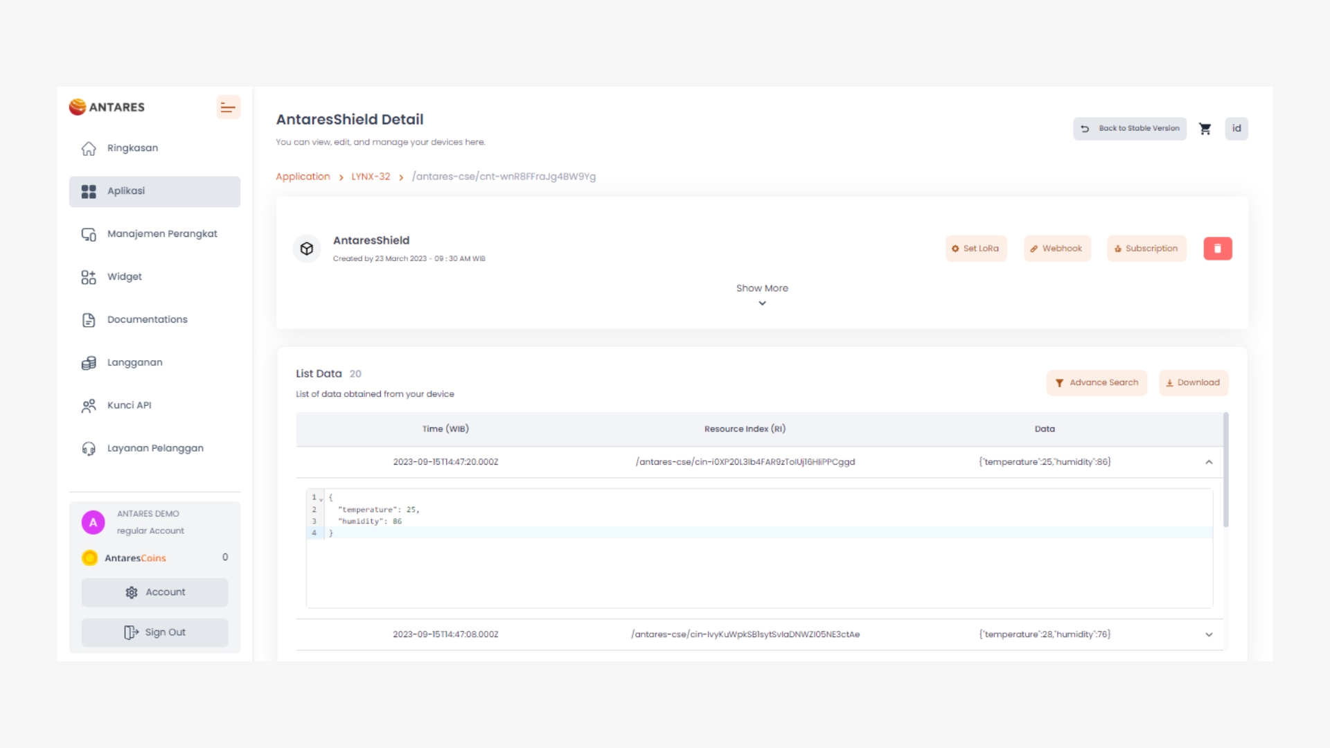
5. Check Data in Antares
After uploading the programme successfully, then open the device antares page and see if the data has been successfully sent.
Data sent from the Lynx-32 Development Board with the HTTP protocol in the form of temperature and humidity variables.