Retrieve Last Data from Antares Server with MQTT Protocol
In this project, you will be directed to retrieve data from Antares IoT Platform to ESP8266 using WiFi connectivity with MQTT protocol.
Prerequisites
The materials required follow the General Prerequisites on the previous page. If you have not prepared the requirements on that page, then you can visit the following page.
General Prerequisites ESP8266 Wi-FiThe additional materials specific to this project are as follows.
Antares ESP MQTT Library. This documentation uses the Antares ESP MQTT library version 1.0.
If you have not installed Antares ESP MQTT version 1.0, you can follow these steps.
Follow These Steps
1. Launch the Arduino IDE application
2. Opening Sample Programme
You can open the programme code in the Arduino IDE via File > Example > Antares ESP HTTP > GetLatestData.
Below is the GetLatestData sample programme code.
3. Set WiFi Credential and Antares Credential in Program Code
Change the HTTP Protocol parameters in the following variables *ACCESSKEY, *WIFISSID, *PASSWORD, *projectName, and *deviceName. Adjust to the parameters in the Antares console.
The *Access key parameter is obtained from your Antares account page.

The WIFISSID parameter is obtained from the name of the Wifi / Hotspot that is currently being used by you. for example in the image below.
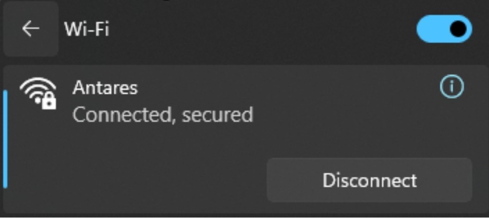
The *PASSWORD parameter is obtained from the WiFi password you are currently using.
The parameters *projectName and *deviceName are obtained from the Application Name and Device Name that have been created in the Antares account.


4. Compile and Upload Program
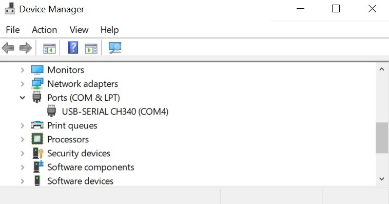
Connect the ESP8266 WEMOS D1R2 with your computer and make sure the Communication Port is read.
On Windows operating systems, checking can be done via Device Manager. If your ESP8266 WEMOS D1R2 is read, the USB-Serial CH340 appears with the port adjusting the port availability (in this case it reads COM4).
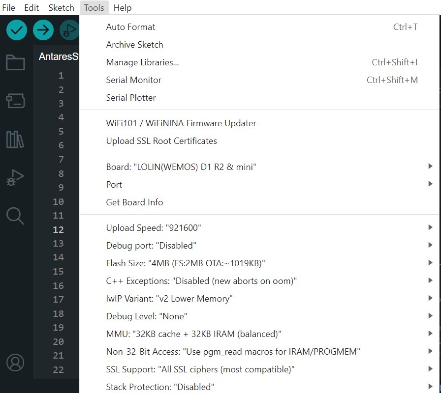
Set up the ESP8266 WEMOS D1R2 board by clicking Tools > Board > esp8266 in the Arduino IDE, then make sure the one used is LOLIN (WEMOS) D1 R2 & mini. Select the port according to the communication port that is read (in this case COM4). The result will look like the following picture.
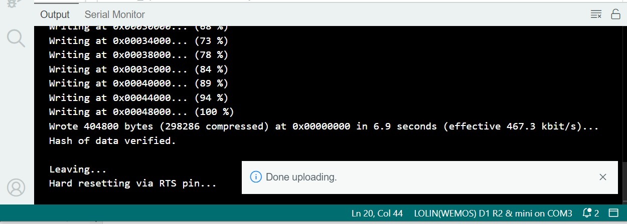
After all the setup is complete, upload the programme by pressing the arrow icon as shown below. Wait for the compile and upload process to finish.

The Tick icon on the Arduino IDE is just the verify process. Usually used to Compile the programme to find out whether there are errors or not. The Arrow icon on the Arduino IDE is the verify and upload process. Usually used to Compile the programme as well as Flash the programme to the target board.
If the programme upload is successful, it will look like the following image.
After uploading the programme, you can view the serial monitor to debug the programme. The serial monitor icon is shown in the following image.

Set the serial baud rate to 115200 and select BothNL & CR. The result will look like the following image.
Make sure the serial baud rate matches the value defined in the programme code. If the serial baud rate is not the same between the programme code and the serial monitor, the ASCII characters will not be read properly.
5. Check Data in Serial Monitor
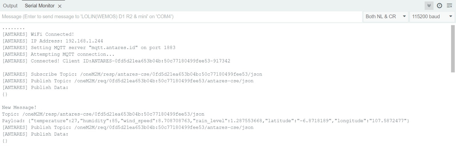
After uploading the programme successfully, then open the Serial Monitor page and see if the data has been successfully retrieved.
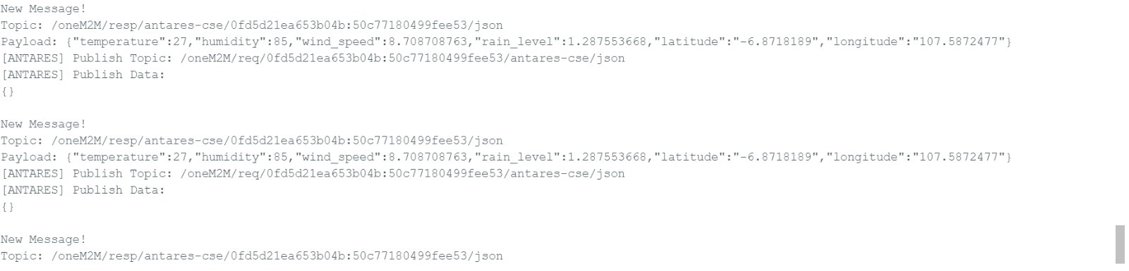


Data retrieved from the Antares IOT Platform is taken using the ESP8266 Board with the HTTP protocol in the form of temperature, humidity, wind_level, rain_level, and location variables containing latitude and longitude.
Last updated