Retrieve Data displayed on OLED Display
PreviousSend DHT 11 data and display on OLED displayNextDHT 11 Send Data and Retrieve Data displayed on OLED Display
Last updated
Last updated
In this project, you will display data from Antares IoT Platform on OLED using ESP8266 module. In this Antares Shield Workshop, there are temperature, humidity (DHT11), relay, LED, and push button sensors. You will send messages in the form of data displayed on the OLED display. The process of sending this data uses MQTTX Software to send data to the Antares IoT Platform.
The materials required follow the General Prerequisites on the previous page. If you have not prepared the requirements on that page, then you can visit the following page.
General Prerequisites ESP8266 Wi-FiThe additional materials specific to this project are as follows.
Shield Workshop Antares
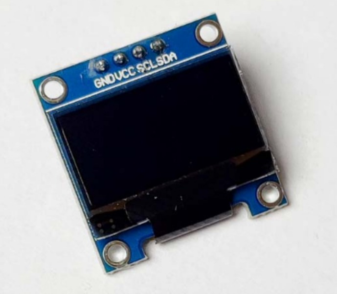
I2C-based 0.96inch 128x64 pixel SSD1036 OLED module
OLED display library. This documentation uses Adafruit_SSD1306 by Adafruit version 2.5.7.
If you have not installed the Adafruit SSD1306 by Adafruit library version 2.5.7. you can follow the steps in the following link.
MQTTX Software
If you have not installed the MQTTX Software, you can follow the steps in the following link.
You can open the programme code in the Arduino IDE via File > Example > Antares ESP MQTT > ESP8266-Simple-Project > RETRIEVE_DATA_OLED.
Below is the programme code of the RETRIEVE_DATA_OLED example.
Change the HTTP Protocol parameters in the following variables *ACCESSKEY, *WIFISSID, *PASSWORD, *projectName, and *deviceName. Adjust to the parameters in the Antares console.
The *Access key parameter is obtained from your Antares account page.
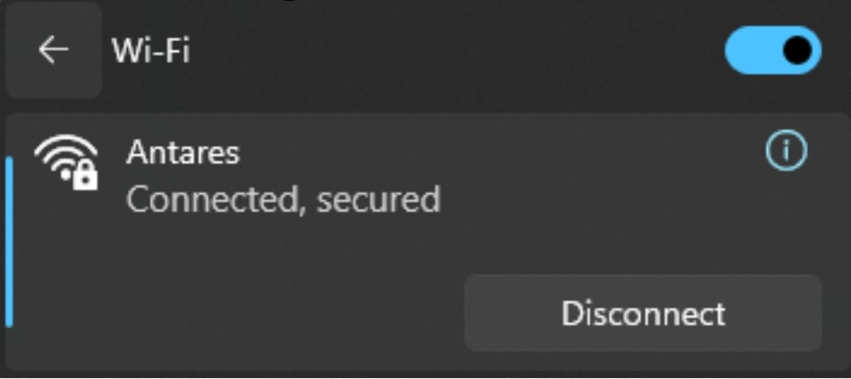
The WIFISSID parameter is obtained from the name of the Wifi / Hotspot that is currently being used by you for example in the image below.
The *PASSWORD parameter is obtained from the WiFi password you are currently using.
The parameters *projectName and *deviceName are obtained from the Application Name and Device Name that have been created in the Antares account.
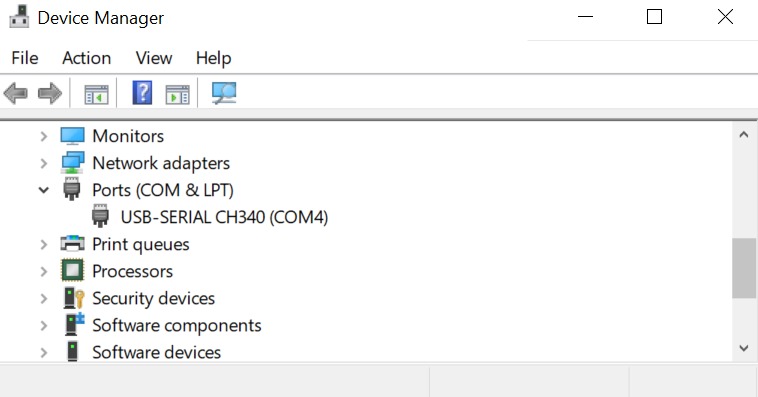
Connect the ESP8266 WEMOS D1R2 with your computer and make sure the Communication Port is read.
On Windows operating systems, checking can be done via Device Manager. If your ESP8266 WEMOS D1R2 is read, the USB-Serial CH340 appears with the port adjusting the port availability (in this case it reads COM4).
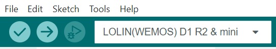
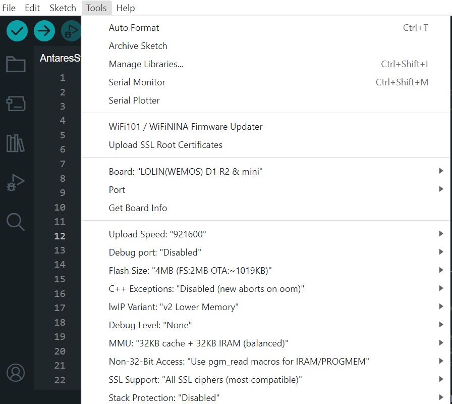
Set up the ESP8266 WEMOS D1R2 board by clicking Tools > Board > esp8266 in the Arduino IDE, then make sure the one used is LOLIN (WEMOS) D1 R2 & mini. Select the port according to the communication port that is read (in this case COM4). The result will look like the following picture.
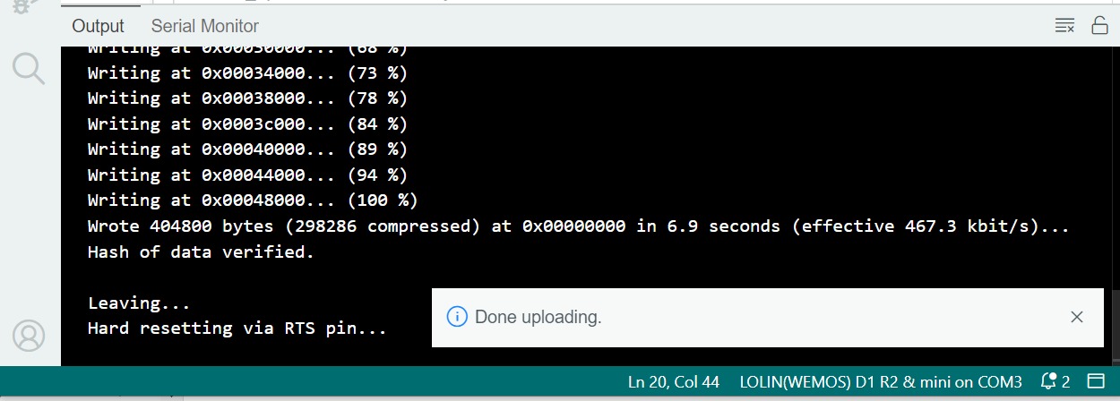
After all the setup is complete, upload the programme by pressing the arrow icon as shown below. Wait for the compile and upload process to finish.
The Tick icon on the Arduino IDE is just the verify process. Usually used to Compile the programme to find out whether there are errors or not. The Arrow icon on the Arduino IDE is the verify and upload process. Usually used to Compile the programme as well as Flash the programme to the target board.
If the programme upload is successful, it will look like the following image.
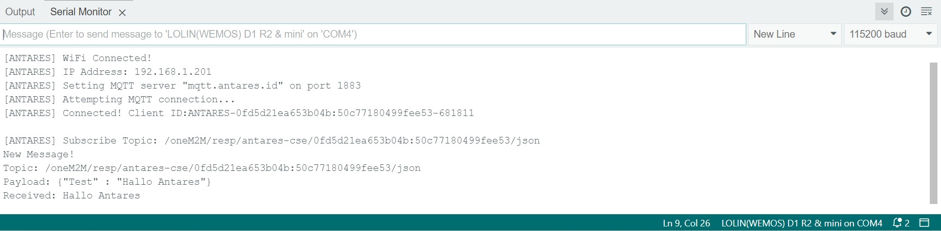
After uploading the programme, you can view the serial monitor to debug the programme. The serial monitor icon is shown in the following image.
Set the serial baud rate to 115200 and select BothNL & CR. The result will look like the following image.
Make sure the serial baud rate matches the value defined in the programme code. If the serial baud rate is not the same between the programme code and the serial monitor, the ASCII characters will not be read properly.
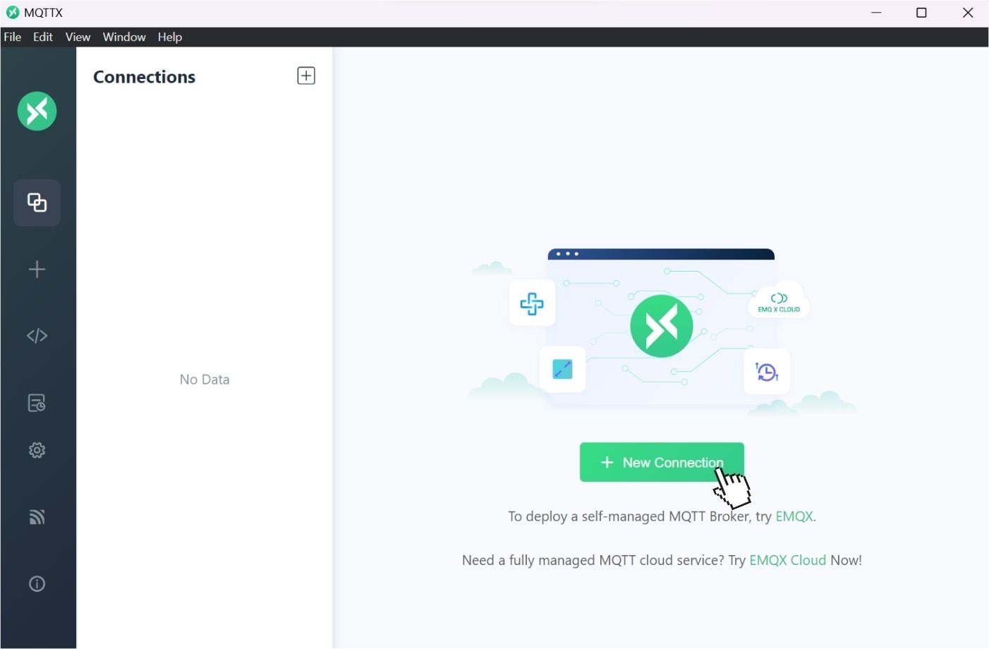
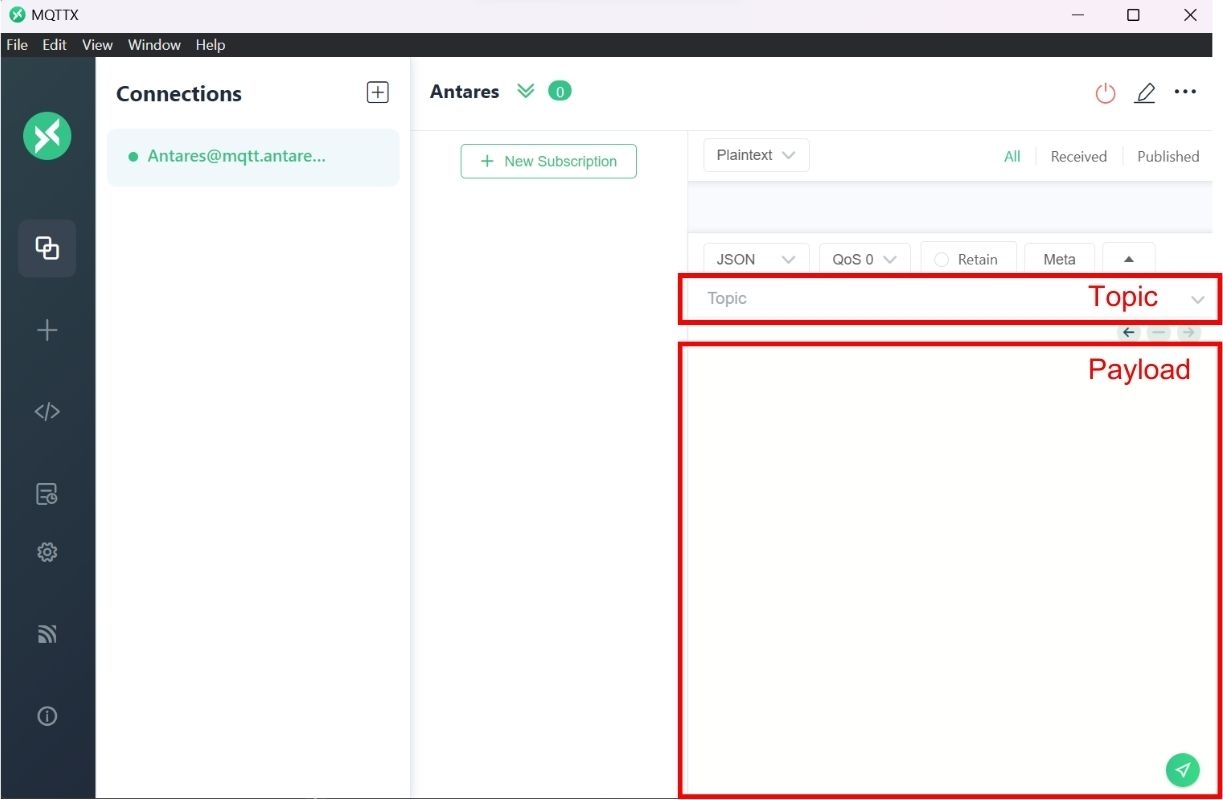
Open the MQTTX App, then select New Connection
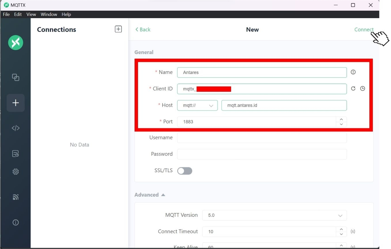
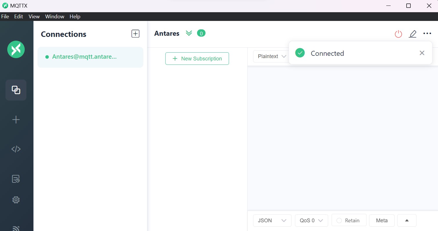
In order to configure MQTTX with Antares broker, adjust the Name, Host and Port as shown below, then click Connect.
If it is connected, there is a notification as shown below
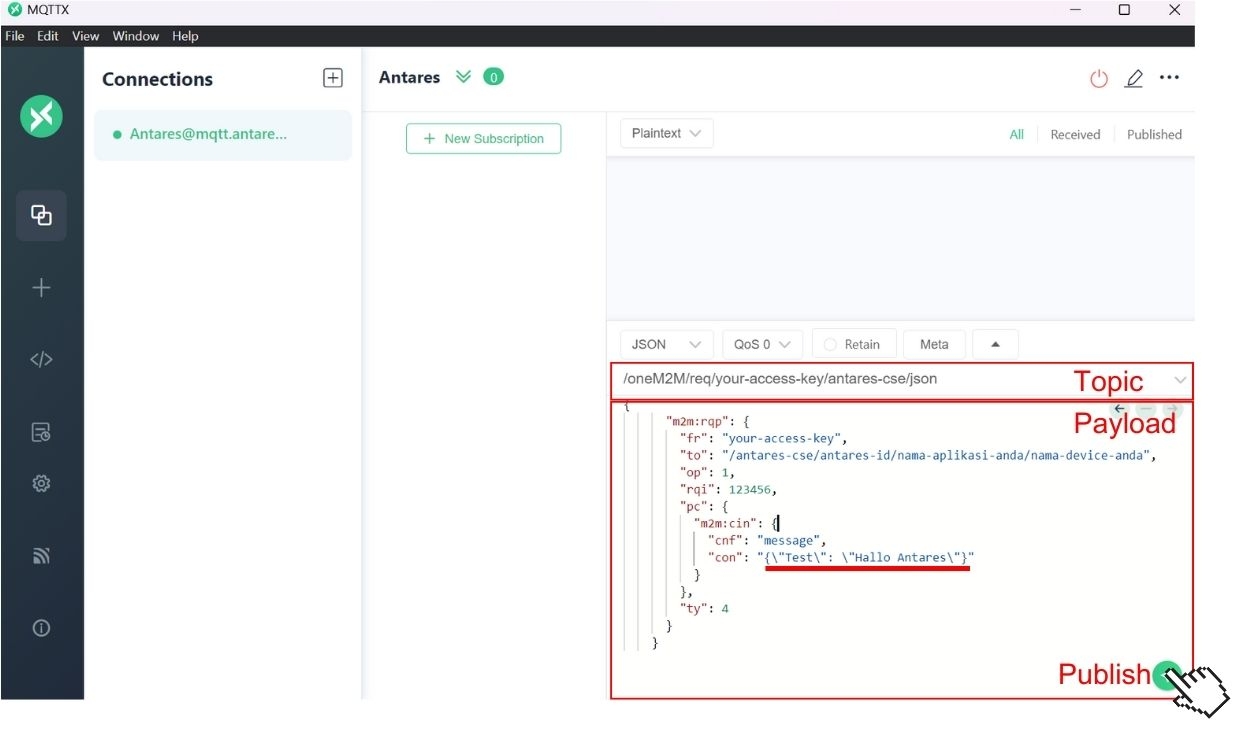
To publish to the Antares server, enter Topic and Payload in the fields in MQTTX.
Topic
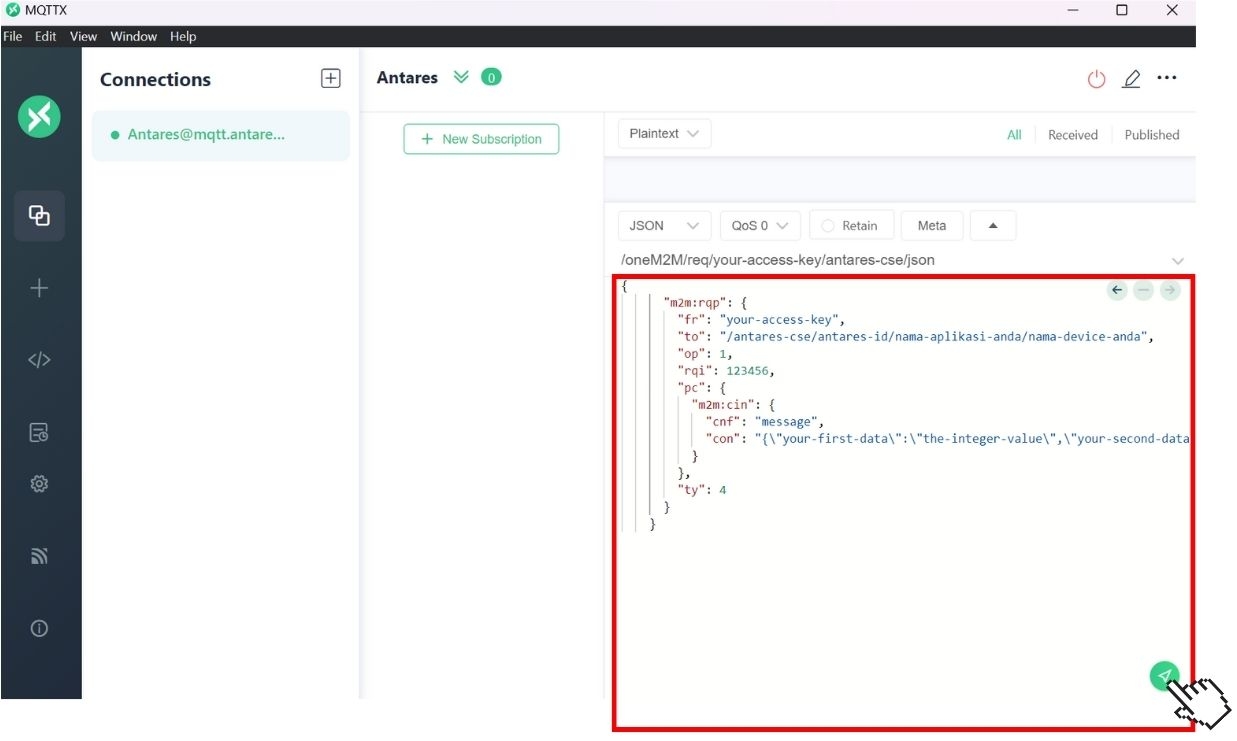
/oneM2M/req/your-access-key/antares-cse/json
Payload
Customise your-access-key, your-application-name, and your-device-name to the names registered to your Antares account. Fill in the "Field" data and "Value" data in "con" as you wish.
In the MQTTX software, enter the Topic and Payload that you want to use. Then click Publish to send the message from MQTTX to the Antares server.
After the MQTTX software setup is complete, it's time to send the PUBLISH command. The "Test" field is filled with the string "Hello Antares" as the message that will be sent via the MQTT protocol to the Antares server.
If you have finished filling in the "Test" field, then press the Publish button on the MQTTX software, as shown below.
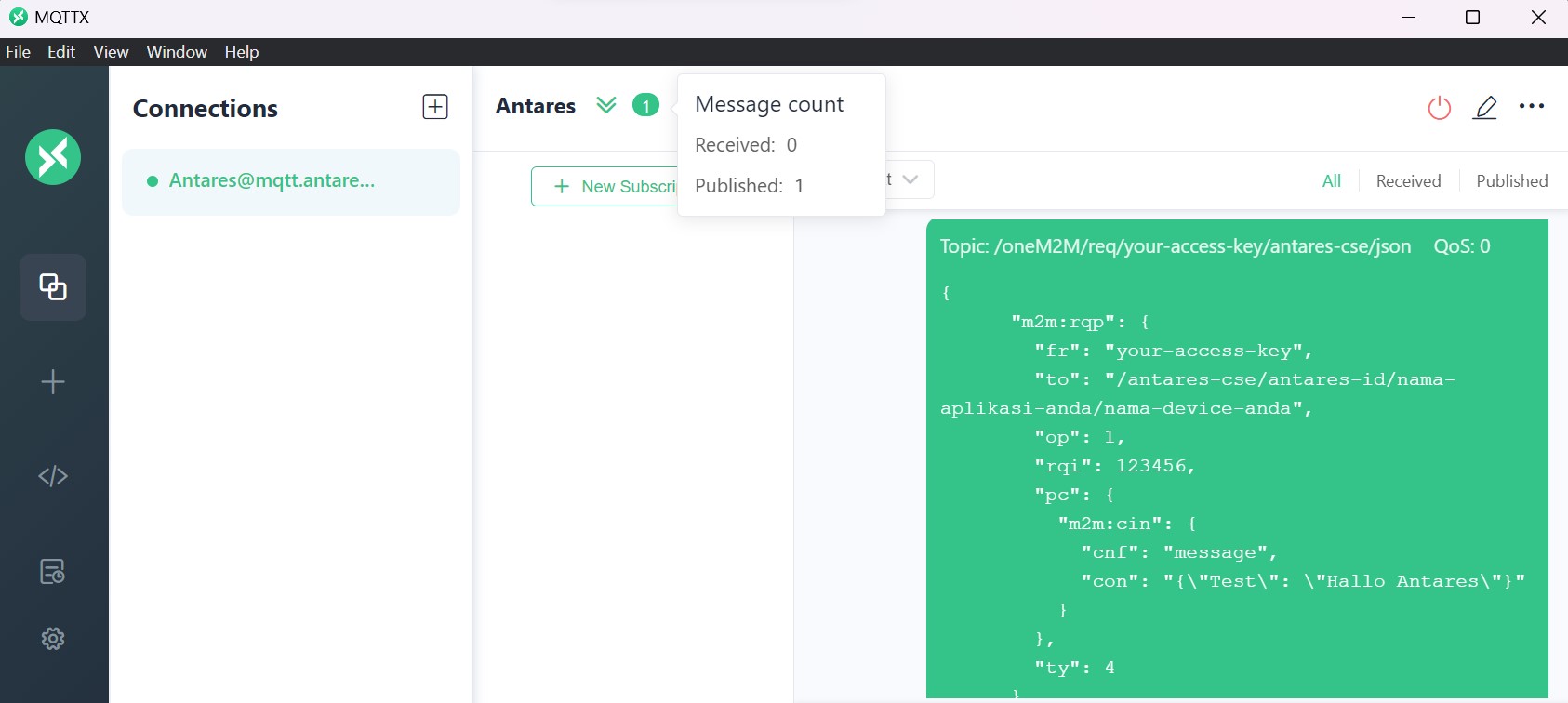
If it has been published, the MQTTX page will have a message like the following.
After uploading the programme successfully, then open the device antares page and see if the data has been successfully sent.
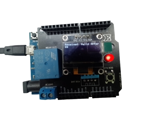
The data received by ESP8266 with MQTT protocol is in the form of Test variable.
Get data from the Antares IoT Platform and display it on the OLED display after connecting to Wi-Fi is shown in the figure below: